AutoCAD XREF: The Secret Weapon of Efficient Design

AutoCAD XREF or External Reference is a powerful feature in AutoCAD that allows you to incorporate external files into your current drawing. Instead of keeping all your linework, labels, and design elements in a single AutoCAD file, XREFs let you break it down into multiple linked files.
As a Site-Civil Design Engineer working on complex projects, I can’t imagine navigating through intricate designs without XREFs. Take a utility sheet, for instance. Instead of having all the existing and proposed linework in one AutoCAD file, I simply XREF the base site plan, survey, and proposed utilities. While all my proposed annotations live in the main utility sheet, the underlying linework exists in separate, manageable XREFs.
What is AutoCAD XREF or External Reference in AutoCAD and its benefits?
XREF or External Reference is a way to bring AutoCAD files as background in current drawing file. There are three key benefits of using XREF.
- Any changes made to the XREF file will automatically update and be reflected in the the current drawing file.
- XREF fosters team collaboration as multiple team members can work different parts of the project at same time.
- Using XREF instead of including all linework and annotations in one CAD file will reduce the file size.
Different Types of XREFs
In AutoCAD, you can attach DWG, Image, DWF, DGN, PDF, Point Cloud (.rcp), and Coordination Model (.nxd). In this blog, we will dive in-depth into attaching DWG, Image, and PDF. To attach any XREF, you must first open the XREF palette, which can be done by typing XREF in the command line.
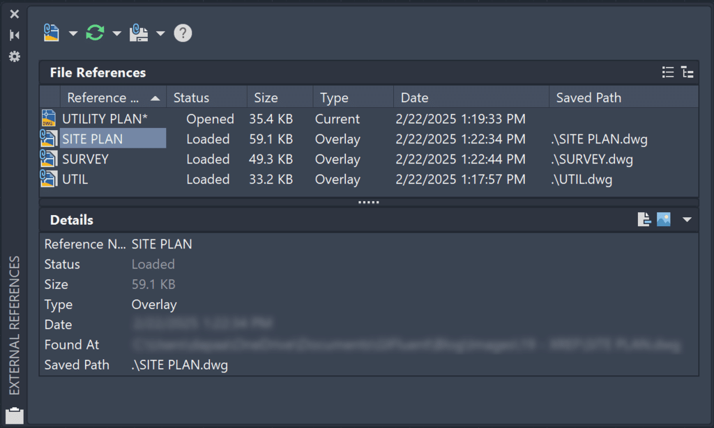
Using External References Palette to Attach DWG File
Once the XREF Palette is opened, choose the DWG option. Navigate through File Explorer to find your AutoCAD file. The Attach External Reference dialog box will open up. You will get the following options:
| Option | Explanation | Image |
| Reference Type | XREFs can be inserted as either an Overlay or an Attachment. An Overlay XREF displays referenced geometry in the background but won’t be included when the current drawing is referenced in other files, preventing circular references. An Attachment XREF becomes part of the current drawing and will be carried along when the drawing is referenced in other files. |  |
| Scale | You can either specify the scale on the screen or enter the scale factor in the Attach External Reference dialog box. | 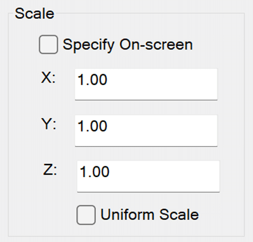 |
| Insertion Point | You can either specify the insertion point on the screen or provide the X,Y,Z coordinates in the Attach External Reference dialog box. |  |
| Path Type | A path type can be No Path, Relative or Full. A No Path references the XREF without and path, and will only work if the referenced file is in the same folder as the current drawing file. A Relative path specifies the location of referenced files in relation to the current drawing’s location, making it ideal for portable project folders where files maintain their relationships. A Full path specifies the complete file location from the root directory. | 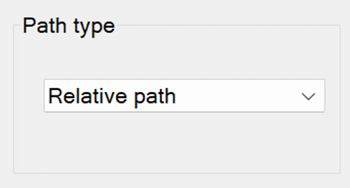 |
| Rotation | You can either specify the rotation on the screen or provide the angle in the Attach External Reference dialog box. | 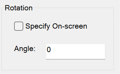 |
| Block Unit | The block unit refers to the units of the drawing. |  |
| Preview | You can see how your XREF looks like. |  |
It is a best practice to put the inserted DWG XREF on a separate layer and ideally lock that XREF. You can lock the XREF by locking the layer on which you put the XREF.
Using External References Palette to Attach Image File
After opening the XREF Palette, select the Image option. Use File Explorer to locate your image file. You will encounter five options similar to those in the Attach DWG option: Path Type, Insertion Point, Scale, Rotation, and Preview.
An image XREF will include an Image Frame. You have three options for editing the Image Border using the IMAGEFRAME variable (0-2).
- Show and Plot No Image Border (IMAGEFRAME = 0)
- Show and Plot Image Border (IMAGEFRAME = 1)
- Show the Image Border but not Plot it (IMAGEFRAME = 2)
In the Image below we are attaching GIFluent Logo in our AutoCAD File. You will generally see Engineering and Architecture Firms attach the image of their company logo on Title block.

Using External References Palette to Attach PDF File
After opening the XREF Palette, select the PDF option. Use File Explorer to locate your PDF file. You will encounter five options similar to those in the Attach DWG and Attach Image option: Path Type, Insertion Point, Scale, Rotation, and Preview.
A PDF XREF will include a PDF Frame. You have three options for editing the PDF Border using the PDFFRAME variable (0-2).
- Show and Plot No Image Border (PDFFRAME = 0)
- Show and Plot Image Border (PDFFRAME = 1)
- Show the Image Border but not Plot it (PDFFRAME = 2)
If the PDF contains multiple pages, you can choose which pages to attach to your sheet. I often use PDF and IMAGE XREFs to add construction details to my construction planset. In the example below we are attaching details of Stormtech Inspection Port Detail into our AutoCAD File.

Working with XREFs
Unloading
If you would like to temporarily turn off an XREF, you can unload it. Simply right-click on the XREF, and choose the Unload option.
Reloading
To turn the XREF back on after unloading it, you can reload it. Additionally, if you made a change in the XREF file and you don’t see the changes in your current drawing, you can reload the XREF to have it updated. Generally when you update an XREF, there will be a pop-up on bottom right of your screen to reload that XREF. Simply right-click on the XREF, and choose the Reload option.

Detaching
If you would like to remove an XREF, you can simply detach it. Only detach an XREF when you know you will not need it. If you want to temporarily remove the XREF from the background, simply unload the XREF. Simply right-click on the XREF, and choose the Detach option.
Clipping
If you want to show only a portion of an XREF, you can clip it. You can activate this option by typing XCLIP in the command line or choosing the Clipping Boundary option in the Ribbon (Select XREF > External Reference > Clipping Boundary). When you XCLIP, you have four primary options:
- Select Polyline: Choose a polyline in the drawing as a clipping boundary
- Polygonal: Draw a polygonal clipping boundary
- Rectangular: Draw a rectangular clipping boundary
- Invert Clip: Hide everything inside the clipped boundary
If you wish to delete the Clipping Boundary, click on the XREF and then on delete Remove Clipping from the Ribbon.
Layer Control
After loading the XREF in your current file, the Layer Properties Palette will display all the layers from your XREF file. This feature is useful for managing your XREF layers effectively.

Changing Path Type
Earlier, we discussed the three types of XREF paths: No Path, Relative Path, and Full Path. If you need to change the path type after attaching an XREF, you can easily do so by following these steps: Right-click on the XREF, select “Change Path Type,” and then choose the new path option you prefer.
Select New Path
If you move your XREF file after referencing it in current drawing, it will no longer be available. In that case you will need to select new path and your XREF will again be available in your current drawing.

XREF Compare
Every time your XREF gets updated and you load it in your current drawing, you can compare the changes. Hit on the next and previous buttons to compare the changes. Checkout the GIF below to see the changes in the XREF.
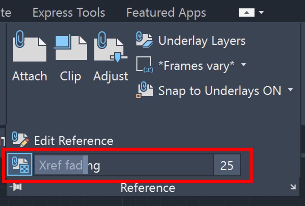
XREF Fading
You can fade your XREF, up to 90%, so that the linework in the current drawing stands out. To fade your XREF (0-90), select your XREF, and follow the following path Insert > Reference > XREF Fading. You can also fade your XREF in the command line by typing XDWGFADECTL and entering the fade percent.
Modifying XREFs
You can modify an XREF without opening the source of the reference file. Simply click on the XREF, choose Edit Reference In-Place option, make changes and hit Save Changes. While its an AutoCAD feature, I do not modify XREF In-Place. I prefer to simply open the XREF file and edit it there.
XREFs help makes your drawing system efficient and ensures multiple people can work on the same project at once. Apart from XREF, there are various other essential AutoCAD features which you can learn from my blog – 25 Foundational Concepts of AutoCAD.


