5 Essential Concepts to Master Units and Limits in AutoCAD

Mastering the fundamentals of units and limits in AutoCAD is crucial for maximizing your productivity. In this blog post, we will delve into choosing units, defining drawing limits, creating customized templates, changing drawing units, and learning how dim style relates to drawing units. Lets get started!
Setting Up and Changing Drawing Units in AutoCAD
The whole point of designing in AutoCAD is to design things accurately and precisely. What you design in AutoCAD, that must be easy to replicate in real world scenario. Units are fundamental in AutoCAD that ensures accuracy and precision.
AutoCAD allows you to work with internationally recognized length measurements, such as feet, meters etc and display them with varying accuracy. Units can be specified in different formats, including decimal and fractional sizes. You can specify whether existing objects in the drawing are scaled to the new units or retain their original size. You can specify whether objects inserted from a drawing that uses different units are scaled to the units in the current drawing, or retain their original size. The precision values specify only the number of decimal places displayed in the interface.
To set up units in AutoCAD, type UN in the command line, and the Drawing Units table will appear. Here, you can set units for length, angle, insertion scale, and lighting. You can also set the level of precision for length and angle.
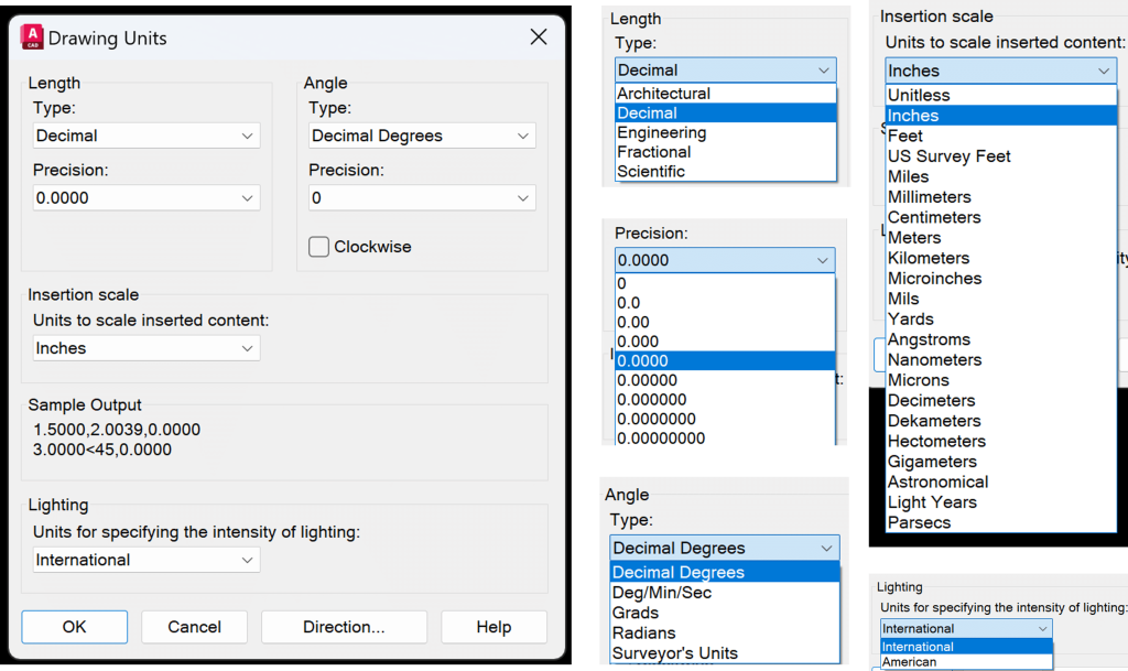
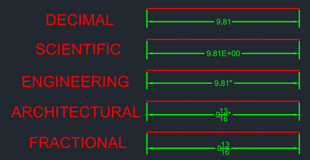
For length, the units available are Architectural, Decimal, Engineering, Fractional, and Scientific. Learn more about each type of length below:
- Architectural: Used in Architectural and Building Design Projects such as floor plans, elevations, and sections.
- Decimal: Commonly used units for various applications from general drafting to engineering.
- Engineering: Used in Civil Engineering, Land Surveyor, and Construction Projects such as site design and land survey.
- Fractional: Used when measurements are best understood in fractions, such as furniture and other manufacturing designs.
- Scientific: Suitable for extremely small or large measurements and for highly precise applications.
The next type of unit available in the Drawing Units Table is Angle. The available units for angle are Decimal Degrees, Deg/Min/Sec, Grads, Radians, and Surveyor’s Units. By default, the angles are measured counterclockwise, but you can update that to clockwise if you wish. Learn more about each type of angle below:
- Decimal Degrees: Represents angle in Decimal Degrees and is the most commonly used format.
- Deg/Min/Sec: This represents the angle in Degrees, Minutes, and Seconds. It is useful when precision to the second is needed.
- Grads: This unit divides a circle into 400 equal parts, and each part is considered one grad. It is used in some European countries for surveying and engineering applications.
- Radians Measure angles based on the radius of a circle. They are used in mathematical and physics calculations. (Remember when your high school math teacher asked you to switch your calculator mode from degrees to radians to get an accurate answer?)
- Surveyor’s Units: Provides angle in Degrees, Minutes, and Seconds, but relative to the true north. They are used in surveying, mapping, and construction applications.

The other unit settings available on the Drawing Units are Insertion Scale, Lighting, and direction control. With Insertion Scale, you can use choose the units for any inserted content, as shown in image below. With Lighting, you can choose between International or American Units. Finally, with direction control you can choose the base angle as shown in image below.
Drawing Limits and Extents
In AutoCAD, drawing limits are used to set invisible rectangular boundary in model space or drawing area to match the size of the sheet. This is really useful when you want to visualize the size of the end product on your screen. One of the most commonly used sheet size is 8.5″ x 11″ or A4 size.
You can set limits in your drawing using the limits command. Follow the steps below to set your limits.
- Step 1: Type LIMITS in the command line. The command prompt will first ask you to specify the coordinates for the lower left corner and then ask you to set the coordinates for the upper right corner in the command line.
- Step 2: Enter the coordinates for the lower left corner and then press enter. For example, you try <0,0>
- Step 3: Next, enter the coordinates for the upper right corner and then press enter. For example, you can try <12,9>. You have successfully created your limits.
- Step 4: Type in Zoom Extents Command to zoom into your limit.
You may mess up your limits by zooming in and zooming out in model space. To ensure that your limits are right or see the visible extent of your limits, you can turn on the grid display just for the limits. To do so change the GRIDDISPLAY Variable to 0. Now the Grid displayed will be only around the limits. Learn more how other values for GRIDDISPLAY function from Autodesk Documentation.

Setting up a template with preferred Units and Limits
Once you have set up preferred units and limits, you can set up a template if you plan to use the same settings in the future. Follow the sets below or GIF below to create you template:
- Step 1: Click on the Application Button
- Step 2: Click on Save As
- Step 3: Click on Drawing Template
- Step 4: Choose the folder where you want to save the Template
- Step 5: The Template is created. Next time you start a new drawing, ensure that you select the template you need before you start your project.
Apart from units and limits, a drawing template also consists of settings for layers, dim style, and leader style. Learn more about layers, dim style, and leader style in my other blogs.
Methods for Changing Units in an Existing Drawing
Method 1: Drawing Units Dialog Box
- Step 1: Type UN in command line. The Drawing Units Dialog Box will appear.
- Step 2: Change the units for length, angle insertion scale and/or lighting. Also choose the precision needed.
- Step 3: Press ok and the units will be updated.
Method 2: Status Bar
- Step 1: Ensure that the UNITS option is on in the Status Bar.
- Step 2: Simply click on Units and change the length units as desired.

Method 3: DWGUNITS
- Step 1: Type DWGUNITS in the command line.
- Step 2: The command prompt will ask you to choose the desired length.
- Step 3: Type in the desired number that corresponds to the unit you wish, and then press enter.

The Status Bar and DWGUNITS methods are efficient if you just wish to change the length units. However, if you wish to change angle, insertion units, direction control, or lighting, you will need to open the Drawing Units Dialog Box.
Dim Style and Units
You can choose to draft your project using the AutoCAD unit of your choice. However, when it comes to annotating lengths or angles, you can change the dim style and showcase dimensions in the units of your choice. You can change the dimension style in the properties panel.

Sum it Up: Mastering Drawing Units and Limits for Efficient Design
Below is a checklist for mastering drawing units and limits in AutoCAD. Mastering these elements will help you boost efficiency and help you become a pro in AutoCAD.
- Change drawing units as needed effortlessly.
- Use the LIMITS command to set limits for your drawing.
- Use the grid display to visualize the drawing limits and units.
- Use dimension style to display the dim annotations based on the format you want.
Hope you enjoyed learning about Units and Limits in AutoCAD. If you are interested in mastering the fundamentals of AutoCAD, feel free to checkout 25 Foundational Concepts of AutoCAD.