9 Key Things about AutoCAD Layout or Paper Space

Once you have your plan or model in Model Space set up, the AutoCAD Layout or Paper Space is where the magic happens for professional printing. This is a critical step which involves creating viewports with precise scaling, setting up layers with plot settings, XREFing in a title block and other important bits that I will cover in this blog.
As a Civil Design Engineer, I spend a lot of time designing plans in the Model Space but I take great care to set up my Layout Tab or Paper Space correctly. These finishing touches turn your technical work into professional deliverables that meet industry standards and client expectations.
Key Differences Between AutoCAD Model Space and Paper Space
You might have already learned about Model Space in my 13 Essential AutoCAD User Interface Guide. Understanding both Model Space and Paper Space (Layout Tab) is vital, as they serve different purposes. Below, I have outlined the key differences between the two in the table.
| Model Space | Layout Tab | |
|---|---|---|
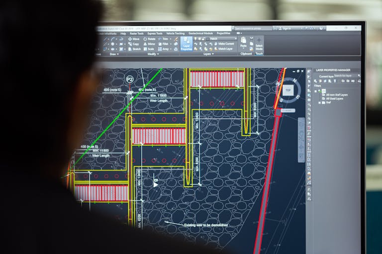
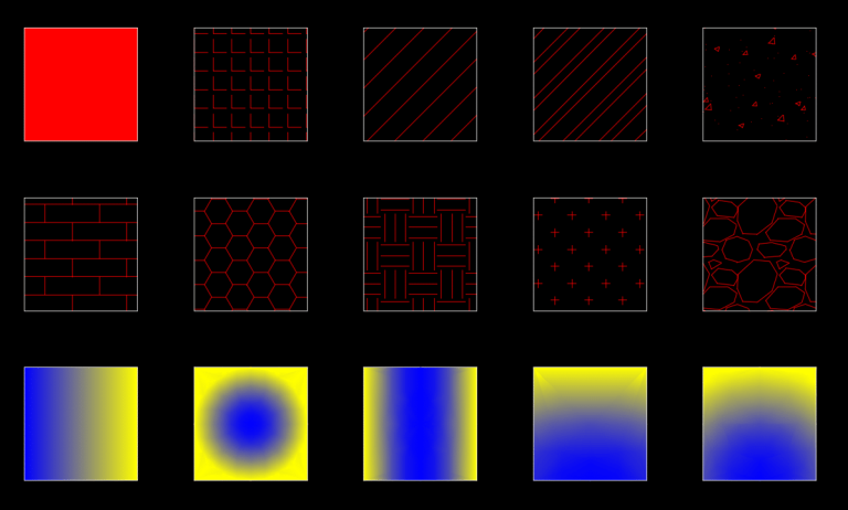
| Image | 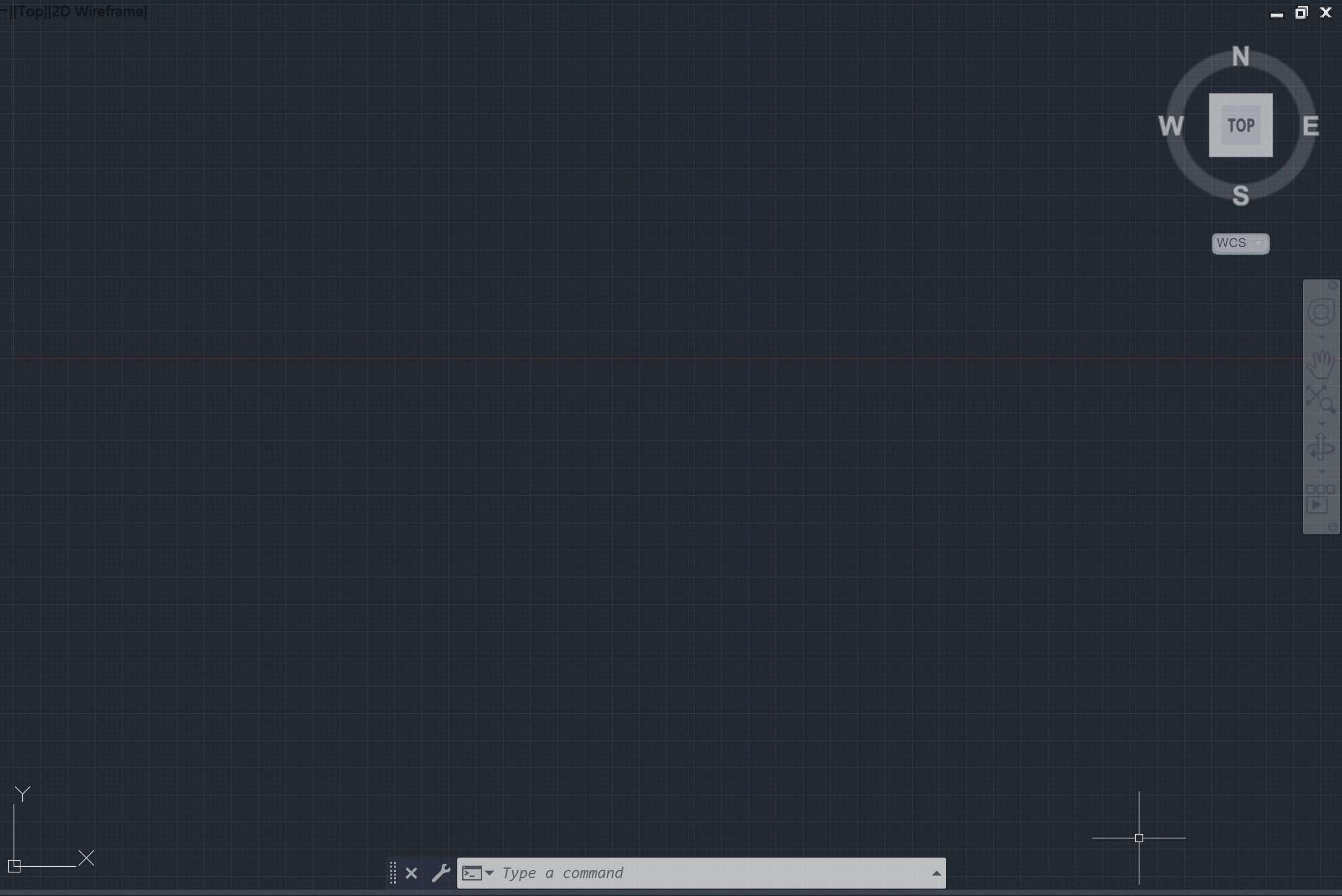 | 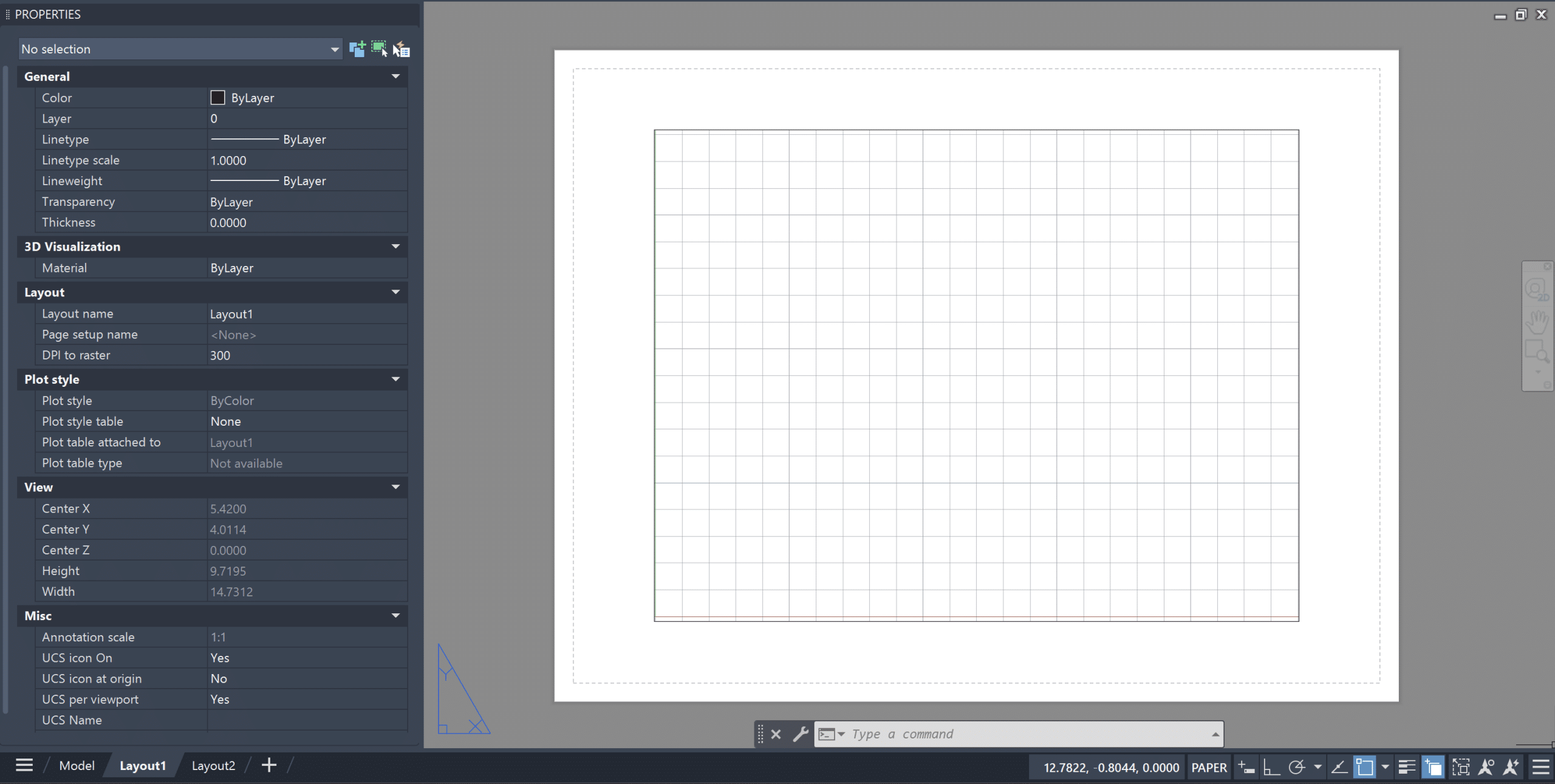 |
| Purpose | All the Design of a plan/model happens in the Model Space. | You prepare how the plan/model will be setup for printing in the paper space. |
| Scale | You can change the scale of the drawing based on the need. | Each Viewport can only have one scale. |
| Content | Contains AutoCAD Objects, Dimensions, Annotations and other elements. | Contains Title Block, Viewport, General Notes and Legends. |
| Units | Uses real-world units such as feet, meters, inches etc. | Uses paper units such as inches and millimeters. |
| Viewports | No Viewports | Viewports are used to show plans or models. |
| Layers | Create and organize layers for objects, annotations, dimensions and other drawing elements | Create and organize layers for layout specific items such as title block, scale, legend, etc. [Putting the Viewport on No Plot layer will ensure the Viewport does not plot] |
| Plotting | Rarely used for plotting. | Ideal for plotting |
| Quantity | There is only one Model Space in a AutoCAD drawing | You can have multiple layout tabs in AutoCAD |
User Interface of Layout Tab (aka Paper Space)
When you open a Layout Tab in AutoCAD, by default you will have a white sheet with a rectangular viewport. Lets look at each element in detail:
- Paper Area: The boundary of the Paper Area is a preview of how your printed product will look like.
- Viewport Boundary: The boundary of the Viewport. You’ll be able to learn more about viewports later in the blog.
- Plot Area Margin: The boundary of the drawing that will be printed.
- Model and Layout Tabs: The tabs are used to switch between model space and paper space.
- Paper Mode and Model Mode: Located in the Status Bar, this button allows you to enter and exit your viewport. It’s useful when you get lost in it and want to come out.

Basic Modify Options in Paper Space
There are six basic modify options with paper space that every AutoCAD user must know – Add a New Layout Tab, Rename Layout Tab, Copy Layout Tab, Move Layout Tab, Change Layout Tab Background Color and Delete the Layout Tab.
Let’s start with the easy ones – adding, renaming, moving and deleting Layout Tabs. To add a new layout tab, click the plus sign next to the Layout Tab. To rename a Layout Tab, right-click on the Layout Tab that you wish to rename, click Rename, and provide a new name. To move a Layout Tab, left-click on the Layout once, and drag it left or right. To delete a Layout Tab, right-click on the Layout Tab that you wish to delete and click on Delete.
To copy a Layout Tab, follow the steps below:
Step 1: Right-Click on the tab that you wish to Copy and choose the Move or Copy option.
Step 2: Choose before which existing Layout the copied Layout should be placed. I generally choose (move to end) option for the copied Layout.
Step 3: Check the Create a Copy option and hit ok.
The Paper Area is white by default but it can be changed to other colors. To change the background color of your Paper Area, follow the steps below:
Step 1: Open the Options Dialog Box by typing OP in the Command Line. Alternatively, you can right-click in the paper area and click on the Options button.
Step 2: Open the Drawing Window Colors Tab by choosing these steps: Display Tab > Window Elements > Colors.
Step 3: Ensure Sheet/Layout is selected in Context options and Uniform Background is selected under the Interface Element option. Then, choose the desired color under the option.


Page Setup Manager in Paper Space
You can open the Page Setup Manager by right-clicking on the Layout tab and then choosing the Page Setup Manager. You will see the following page setup details: – Device Name
– Plotter
– Plot Size
– Where
– Description
To ensure that the Page Setup Dialog Box opens up each time you create a new Layout Tab, make sure to check the Display When Creating a New Layout button in the lower-left corner of the dialog box.

You can hit modify to edit page setup settings. While most of the options are about plotting the sheet, one option is essential as the first set of Page Setup – Paper Size. Unless you have the paper size correct, you will not be able to proceed with other aspects of setting up the layout tab. To change the paper size, follow the steps below:
- Open the Page Setup Manager (Right-click on the Layout Tab and choose the Page Setup option)
- Click on the Modify Button to open the Page Setup Dialog Box
- Change the Paper Size
You can also open the Page Setup Manager dialog box by typing PAGESETUP in the command line or from Ribbon Area (Layout > Layout > Page Setup).
All About AutoCAD Layout Viewports
Viewports are a major feature of AutoCAD Layout, helping translate your model into a printed plan. Understanding how to create, modify, and deal with viewports is essential for streamlining the process of setting up paper space and eventually plotting it.
Create a Viewport in AutoCAD
Two major commands are used for creating viewports in AutoCAD: MVIEW and VPORTs. The MVIEW option is ideal if you want to create a custom viewport and VPORTs option is ideal if you want to create preconfigured viewports.
You can activate the MVIEW command by typing MVIEW in the command line or from the Ribbon Area (Layout > Layout Viewports > MVIEW). Now, choose a corner point in the Paper Area to start the viewport and also choose a corner point diagonal to the first point. You will notice that once you activate the MVIEW command, there are many options in the command line which helps with further customization.

You can activate the VPORTS command by typing VPORTS in the command line or from the Ribbon Area (Layout > Layout Viewports > VPORTS). Once you activate it, the Viewports Dialog Box will open up. Below is a list of standard viewports and other settings:
Standard Viewports:
- Single
- Two: Vertical
- Three: Right
- Three: Left
- Three: Above
- Three: Below
- Three: Vertical
- Three: Horizontal
- Four: Equal
Settings:
- Viewport Spacing
- Setup (2D/3D)
- Change View To
- Visual Style

Locking Viewport Scale
Once you set the limits and scale of a viewport, it is ideal to lock the viewport. You can do so by clicking inside the viewport and then selecting the lock button in the Status Bar.
One mistake I used to make as a novice Civil Design Engineer was keeping the Viewport unlocked while editing my plans. At times, I would accidentally zoom into the Viewport, which would change the scale of the drawing. One quick fix is to undo it simply.


Edit the Viewport Boundary and Viewport Scale in AutoCAD
You can edit the Viewport Boundary by dragging the grips at the end of the viewport. If you wish you can also clip the boundary of the viewport. You can change the scale of the viewport in three ways:
- Status Bar: Double click inside a viewport and change the drawing scale from the options in Status Bar.
- Down Triangle Arrow: Click on the Down Triangle Arrow next to the Viewport Base Point and choose a scale.
- Properties Panel: Select the Viewport and change the scale of the viewport from options in Properties Panel.


Copy and Move Viewport in AutoCAD
You might want to copy a viewport to have it on the same layout sheet, have it on different layout sheet or to a different AutoCAD file. You can copy viewport the same way you can copy AutoCAD objects. While I did cover how to copy objects in my blog AutoCAD Intuitive Commands, let’s do a quick refresher.
Copy Viewports for the same Layout in AutoCAD:
Type CO in the command line, select the viewport you desire to copy, and then place it where it is needed.
Copy Viewports between Layouts in AutoCAD:
Type COPYCLIP in the command line (or use CTRL+C), select the viewport to be copied, go to the desired Layout Tab, and type PASTECLIP in command line (or use keyboard shortcut CTRL+V).
Copy Viewports between two AutoCAD Files in AutoCAD:
Type COPYBASE in the command line, specify base point, select the Viewport, and then type PASTECLIP in command line (or use keyboard shortcut CTRL+V). You can use this method for copying viewports between layouts too.
Moving a Viewport in AutoCAD
You can move a viewport in AutoCAD by clicking and dragging the base point. You can also activate the Move command, select the viewport, and move the Viewport.
Delete a Viewport in AutoCAD
To Delete a Viewport in AutoCAD, simply click on the Viewport in the Layout Tab and hit delete.
Layer Management for Viewport Plot/Preview
In most cases I will take care of Layer Management of my drawing or model in the Model Space unless they are Paper Space Elements. It is essential to set the layers to right plot style to ensure that when you preview the viewport, you mirror how the plot file will look like.
When you open the Layer Properties Manager in the viewport, you will see additional options – VP Color, VP Linetype, VP Lineweight, VP Transparency, and New VP Freeze. If you want a layer to look different or have different properties in the Model Space and Paper Space, then AutoCAD does give you this opportunity.
In my career so far, I have never kept my Model Space and VP Space layer settings different. The only use case I can think of is if you are placing some Layout Elements on the same layer as the Model Space Elements, then you would want different settings for each. But in that case, I would simply put them on different layers and keep things clean.

Title Block and Fields (aka Smart Text)
Title Blocks in Layout Plans provide essential identification, project details, and professional credentials to establish document standardization and legal accountability. Generally Fields or Smart Texts are used to control Sheet Names Sheet Numbers.
North Arrow & Scale
Generally you will also have a north arrow and scale bar in the Paper Space. You can create a symbol and save them as blocks. Autodesk recognizes the need for a dynamic North Arrow and Scale Bar. In many AutoDesk products, you can create North Scale and Scale Arrow by simply selecting the viewport and choosing either North Arrow or Scale Bar from the Layout Option in Ribbon Area.
Hope you enjoyed learning about AutoCAD Layout. To learn more about other aspects of AutoCAD, feel free to checkout 25 Foundational Concepts of AutoCAD.