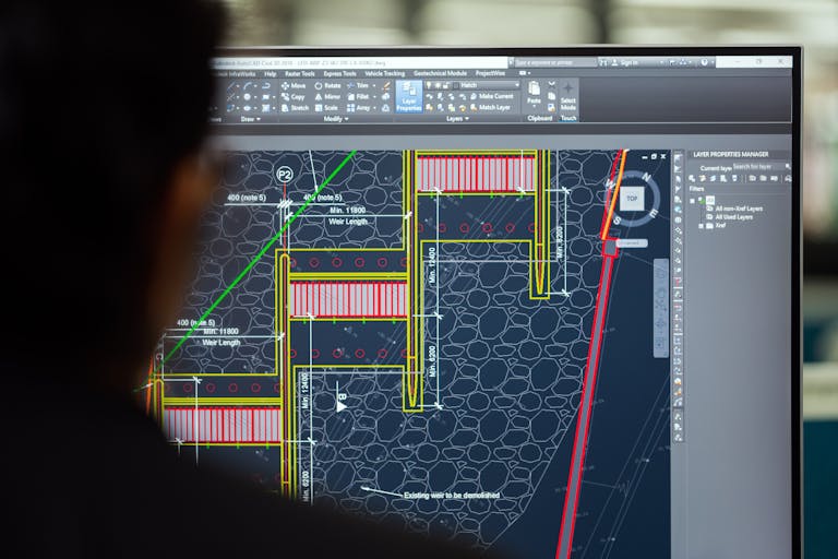
The Ultimate Guide to AutoCAD Dimensions

AutoCAD Dimensions are the storytellers of a plan or design. The measurements reflected by these dimensions tell the design intent and help transform two-dimensional drawing into three-dimensional real world objects. However, many AutoCAD users either underutilize the dimension features or do not use them optimally. In this blog, I will unlock the various facets of dimensioning in AutoCAD and cover various dimension types, from linear dimension to jogged linear dimension.
Create Dimensions in AutoCAD
Linear Dimensions
What does the DIMLINEAR command in AutoCAD do?
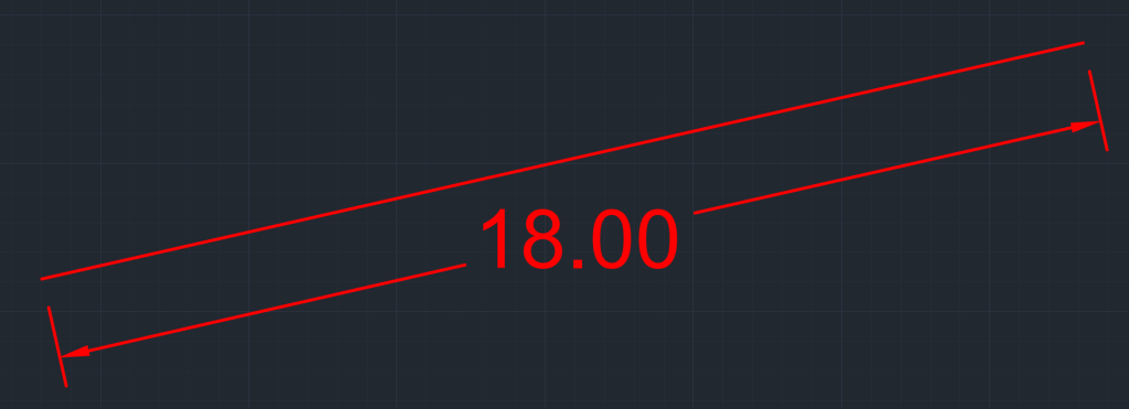
The DIMLINEAR command indicates the distance between two points. This linear extent could be horizontal, vertical or at an angle. It is ideal for straight lines.

How to use the DIMLINEAR command in AutoCAD?
You can activate the DIMLINEAR command by typing DIMLIN in the command line or choosing the Dim Aligned option from the Ribbon (Annotate > Dimensions > Linear).
You can choose the starting and end points or the object to create a linear dimension. Activate the command and select the start and end points to create linear dimension. To create a linear dimension by selecting an object, press enter after activating the command and select the object.
Some of the customization options available with this option are Mtext, Text (Change Dim Text), Angle, Horizontal, Vertical, and Rotated.
Aligned Dimension
What does the DIMALIGNED command in AutoCAD do?
The DIMALIGNED command will dimension an object by aligning or tilting it to the same angle as the object.
How to use the DIMALIGNED command in AutoCAD?
You can activate the DIMALIGNED command by typing DIMALI in the command line or choosing the Dim Aligned option from the Ribbon (Annotate > Dimensions > Aligned).
Choose the first point where you want to start the dimension, and then choose the end point where you want to end the dimension. There are three customization options available with this type of dimension – Mtext, Text and Angle.
Angular Dimensions
What does the DIMANGULAR command in AutoCAD do?
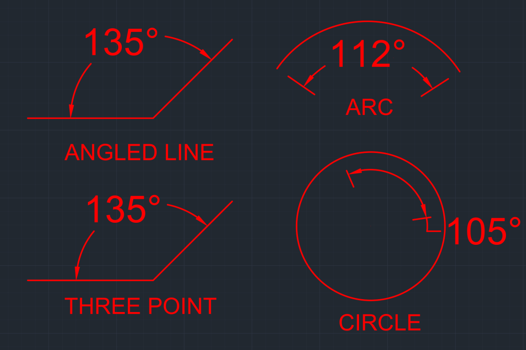
The angular dimension or DIMANGULAR command in AutoCAD will annotate angles through line selection, in an arc, in a circle, and by choosing three points.
How to use the DIMANGULAR command in AutoCAD?
You can activate the DIMANGULAR command by typing DIMANG in the command line or choosing the Angular option from the Ribbon (Annotate > Dimensions > Angular).
As mentioned earlier, you can create angular annotation for line, arc, circle or choosing three points. Below are key points that you need to pay attention for creating an angular annotation for each element:
- Angled Line: Select the two lines between which you want to find the angle.
- Arc: Choose the arc whose angle you want to find.
- Circle: Select the circle whose angle you want to annotate. Note the point at which you first select the circle will become the first point and then you will have the option to choose the second point.
- Three Points: When using this option, the first point is the angle vertex between the two points and the remaining points are the endpoints.
Arc Length Dimension
What does the DIMARC command in AutoCAD do?
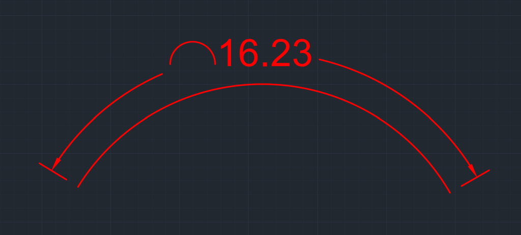
The DIMARC command will annotate the length of a polyline arc segment.
How do you use the DIMARC command in AutoCAD?
You can activate the DIMARC command by typing DIMARC in the command line or choosing the Arc Length option from the Ribbon (Annotate > Dimensions > Arc Length).
Once the command is activated, select the arc, and an arc annotation will be created. You will have the following customization options with it:
- MText: Converts the arc length annotation from text to Mtext.
- Text: Changes the text of the arc length to the desired text, which can also be done by double clicking on the arc length and updating it.
- Angle: You can put the arc length text at the desired angle.
- Partial: Annotate the partial length of an arc.
- Leader: Adds a leader to arc length annotation.
Radius Dimensions
What does the DIMRADIUS command in AutoCAD do?
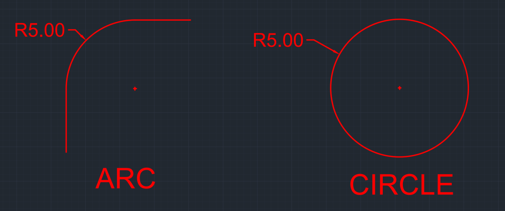
The Radius Dimensions or DIMRAD command annotates the radius of an arc or a circle. I often use it to annotate curbs in proposed site layouts.
How do you use the DIMRADIUS command in AutoCAD?
You can activate the DIMRADIUS command by typing DIMRAD in the command line or choosing the DIMRAD option from the Ribbon (Annotate > Dimensions > Arc Length).
Select a radius or an arc, and it will generate the radius annotation. Like DIMARC, the DIMRADIUS annotation also has the customization of MText, Text and Angle.
Diameter Dimensions
What does the DIMDIAMETER command in AutoCAD do?
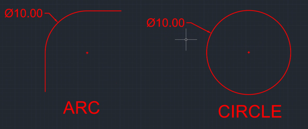
The Diameter Dimension or DIMDIAMETER command annotates the diameter of an arc or a circle.
How do you use the DIMDIAMETER command in AutoCAD?
You can activate the DIMDIAMTER command by typing DIMDIA in the command line or choosing the DIAMETER option from the Ribbon (Annotate > Dimensions > Arc Length).
Simply select a radius or an arc, and it will generate the diameter annotation. Similar to DIMARC, the DIMDIAMETER annotation also has the customization of MText, Text and Angle.
Jogged Radius Dimension
What does the DIMJOGGED command in AutoCAD do?
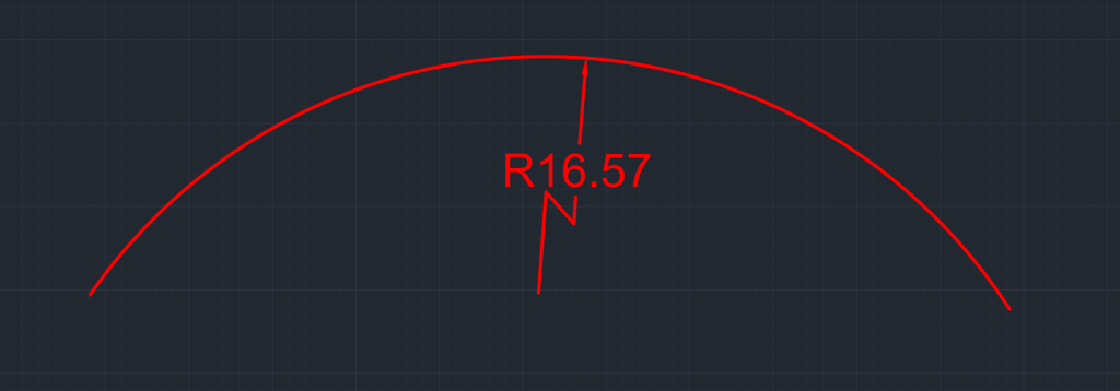
The DIMJOGGED command adds a jogged radius dimension by selecting an arc or circle.
How do you use the DIMJOGGED command in AutoCAD?
You can activate the DIMJOGGED command by typing DIMJOGGED in the command line or choosing the JOGGED option from the Ribbon (Annotate > Dimensions > Jogged).
Simply select the arc, specify a center location, and then the location of the jogged line to create a jogged dimension. Similar to DIMARC, the DIMJOGGED annotation also has the customization of MText, Text, and Angle.
Jogged Linear Dimension
What does the DIMJOGLINE command in AutoCAD do?
The DIMJOGLINE command adds a jog line to existing linear or aligned dimensions.

How do you use the DIMJOGLINE command in AutoCAD?
You can activate the DIMJOGLINE command by typing DIMJOGLINE in the command line or choosing the JOGLINE option from the Ribbon (Annotate > Dimensions > Dimjogline).
To create jogged dimensions, activate the command, select the dimension, and choose the point on the dimension where you want the jog to be added.
Ordinate Dimensions
What does the DIMORDINATE command in AutoCAD do?
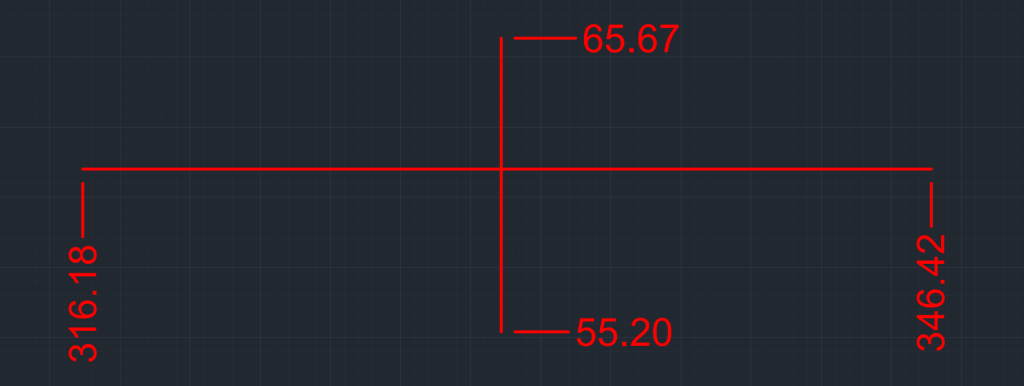
The ordinate dimensions or DIMORDINATE command measures the perpendicular distance in both horizontal and vertical direction (X&Y) from a chosen origin or center point.
How do you use the DIMORDINATE command in AutoCAD?
You can activate the DIMORDINATE command by typing DIMORD in the command line or choosing the ORDINATE option from the Ribbon (Annotate > Dimensions > Ordinate).
To add an ordinate, activate the ordinate command, and select the the center or origin point. Drag the cursor in X&Y direction for the needed distance. In the command line, you will have the option for XDatum & YDatum in addition to MText, Text and Angle. When you select the XDatum option, the movement of the ordinate dimension will be limited in the X-direction. When you select the YDatum option, the movement of the ordinate dimension will be limited in the Y-direction.
Baseline Dimension
What does the DIMBASELINE command in AutoCAD do?
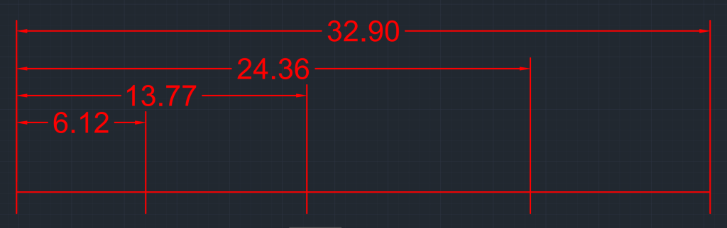
The DIMBASELINE command generates multiple dimensions that are parallel to each other, all originating from the same base point.
How do you use the DIMBASELINE command in AutoCAD?
You can activate the DIMBASELINE command by typing DIMBASELINE in the command line or choosing the DIMBASELINE option from the Ribbon (Annotate > Dimensions > Baseline).
To use the Baseline command you will need to have created a linear or aligned dimension with the base point, also known as base dimension. After that activate the baseline command, select the existing dimension, and choose new dimension points.
Continue Dimension
What does the DIMCONTINUE command in AutoCAD do?
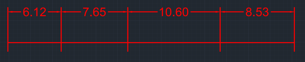
The DIMCONTINUE command creates continued dimensions where a new dimension starts from the endpoint of the previous dimension.
How do you use the DIMCONTINUE command in AutoCAD?
You can activate the DIMCONTINUE command by typing DCO in the command line or choosing the DIMCONTINUE option from the Ribbon (Annotate > Dimensions > Continue).
To use the Continue command, you must have created a linear or aligned dimension with the base point. After that, activate the continue command, select the existing dimension, and choose new dimension points.
Quick Dimension
What does the QDIM command in AutoCAD do?
The Quick Dimension or QDIM command creates different types of dimensions from the selected object in sequence.
How do you use the QDIM command in AutoCAD?
You can activate the Quick Dimension command by typing QDIM in the command line or choosing the Quick option from the Ribbon (Annotate > Dimensions > Continue).
The QDIM provides the following command prompt – Continuous, Staggered, Baseline, Ordinate, Radius, Diameter and Datum Point. I have covered the details of all these dimensions except staggering. The staggering option will add dimension in a staggered or alternating fashion to prevent overcrowding of dims.
Dissecting Components of a Dimension Line
- Dimension Value/Measured Value
- Text Height
- Arrow Size
- Arrow 1
- Arrow 2
- Dimension Line 1
- Dimension Line 2
- Extension Line 1
- Extension Line 2
- Extension Line Offset
- Extension Line Ext

AutoCAD Dimension Style Manager
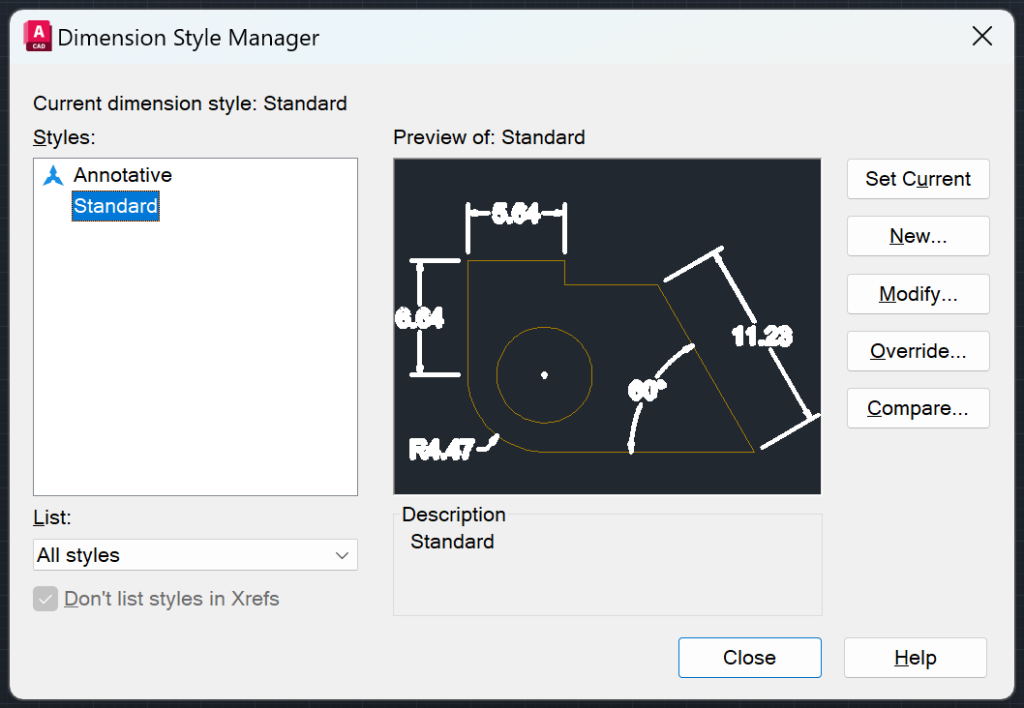
Dimension styles, much like text styles, play a crucial role in ensuring consistency in the presentation of dimensions within a drawing. They also contribute to a professional appearance. To create a new Dimension Style, you can either type DIMSTYLE in the command line or navigate to the Ribbon by selecting Annotate > Dimensions > Dimension Styles > Manage Dimension Styles. From there, you can choose an existing style or create a new one. If you opt to create a new style, you will be presented with numerous customization options, which are explained below.
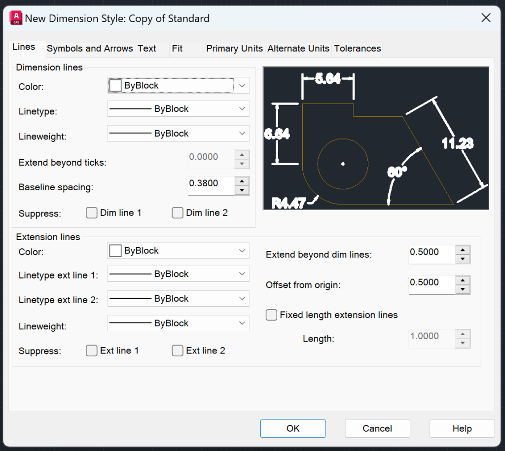
Lines
The line tab comprises options to customize Dimension Lines and Extension Lines such as color, line type, line weight etc.
Symbols and Arrows
The Symbols and Arrows tab comprises options to customize Arrowheads, Center Marks, Dimension Break, Arc Length Symbol, Radius Jog Dimension, and Linear Jog Dimension.

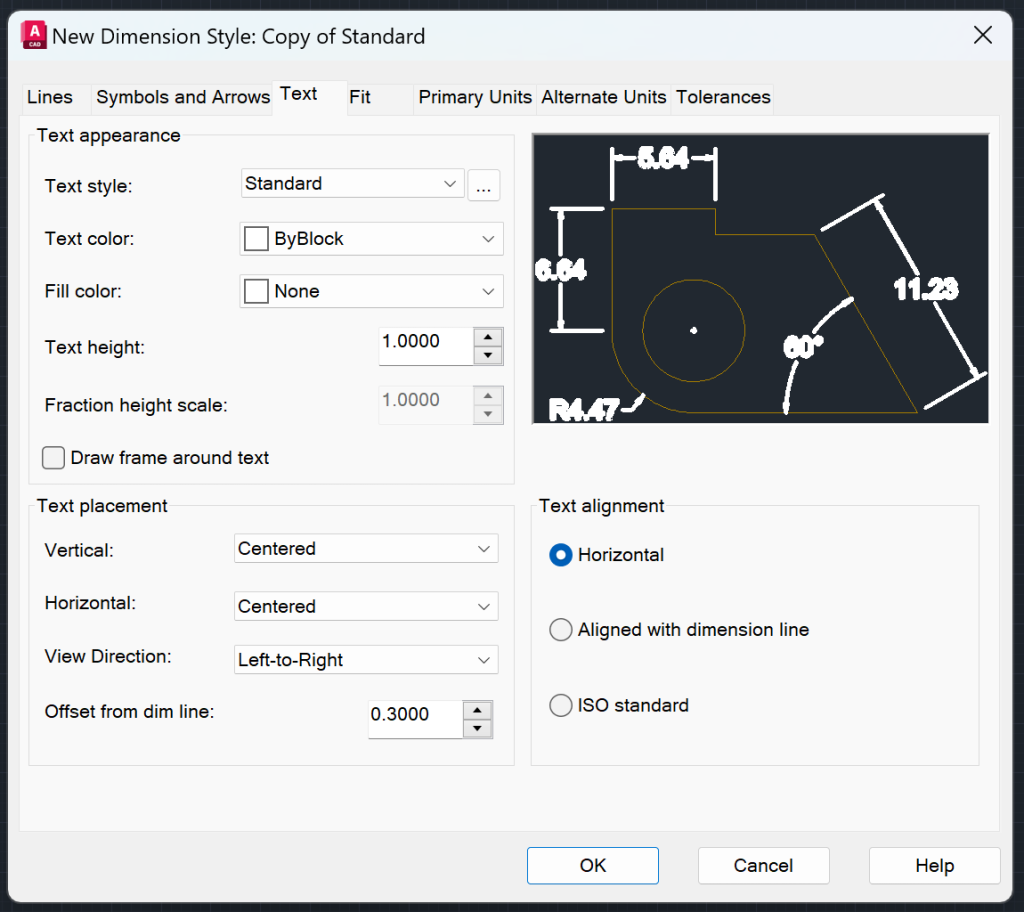
Text
The Text Tab comprises options to customize Text Appearance, Text Placement, and Text Alignment.
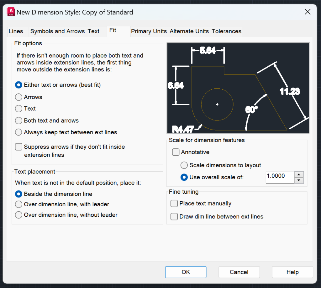
Fit
The Fit tab comprises options to customize Fit Options, Text Placement, Scale for Dimension Features, and Fine Tuning.
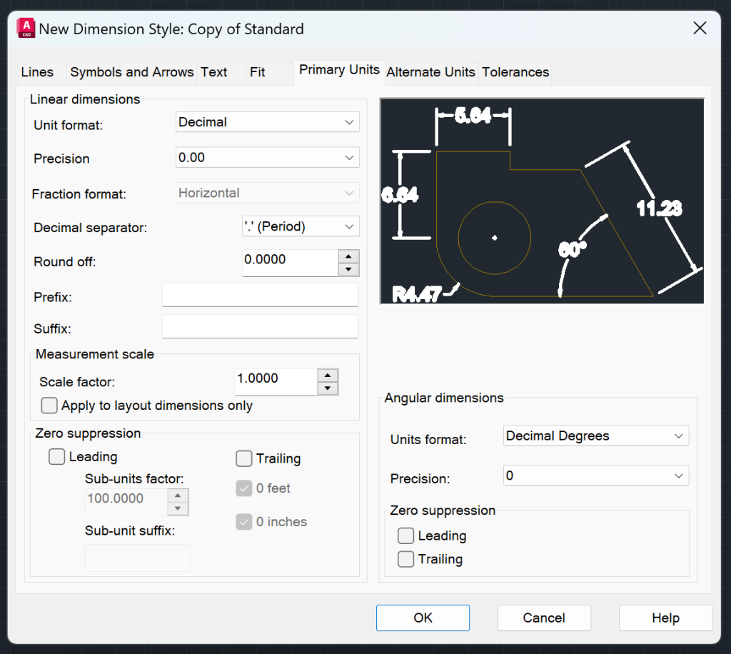
Primary Units
The Primary Units tab comprises options to customize Linear Dimensions, Zero Suppression, and Angular Dimensions.
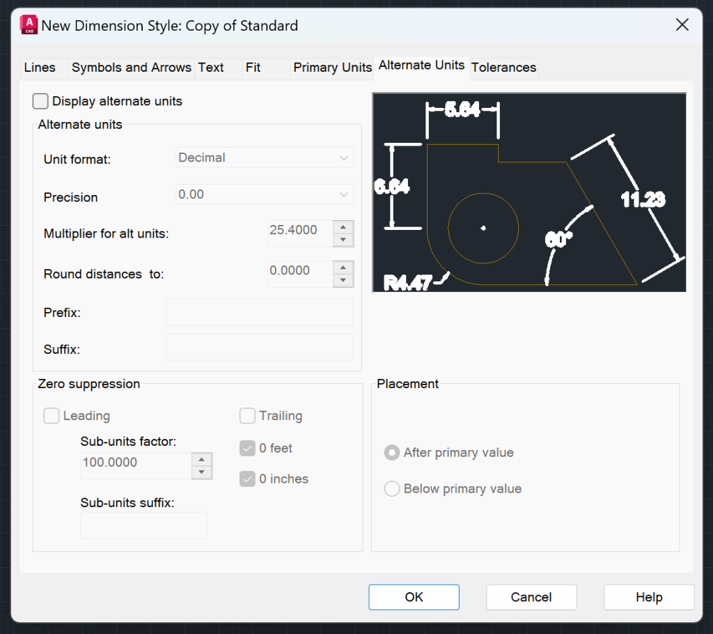
Alternate Units
The Alternate Units tab comprises options to customize Alternate Units, Zero Suppression and Placement.
Tolerances
The Tolerances tab comprises options to customize Tolerance Format, Tolerance Alignment, Zero Suppression, Alternate Unit Tolerance, and Zero Suppression.

Other Components of Dimension Style Manager
Set Current – Makes the selected style to the current dimension style
Modify – Change the settings in a Dimension Style
Override – Override properties of Dimension Style
Compare – Compare differences between two styles
List – With this drop down list you can choose which type of styles you want to see in the Styles section.
Hope you enjoyed learning about AutoCAD Dimensions. To learn more about other aspects of AutoCAD, feel free to checkout 25 Foundational Concepts of AutoCAD.